Introduction
Last April, I have recorded a video of Marozzo’s spada sola (more details in the corresponding post). The initial goal was to perform the drill of course, but as I looked at what I had, I realized it could be used for something else as well.
As it happens, there are three vertical cuts in the set, and I had a video from the side. This is precious because this combination of cutting and shooting angles is creating the least distortion due to perspective effects. The video therefore captured the trajectory of a cutting sword very clearly, in such a way that I could analyze it quite precisely. Shooting on a sunny day also minimized motion blur on each frame, so I could record the sword’s position with good accuracy. I had anticipated this application and attached a hair tie on the blade at the node of vibration to make it easier to track. The technique and recording conditions were helping to solve most of the problems faced by Sean Franklin in his own attempt.
Further, I also have taken measurements of my sword (the lovely Danelli sidesword), of course. With not only mass and lengths, but also radius of gyration, and the sequence of positions extracted from the video, I could (in theory at least!) compute speed, energy, acceleration, even forces. This was an opportunity to dissect an actual cut and get some idea of the mechanics at play!
After looking around a bit I did not find a satisfying existing solution that would let me easily do all the custom computations I had in mind, so I set out to write my own video analysis tool in Javascript – making it easy to tie it to my Weapon Dynamics Computer. It has been a lot of work, but worth it in my opinion.
In this post I will share some results from this analysis, performed on the first of the three vertical cuts. I have elected to focus on this one because it had the clearest start and stop, flowing from an horizontal guard and falling to a guard. The second and third fendente in the sequence blend into one another, which makes the analysis more complex.
The raw cut
Here is an animated GIF created from the sequence of frames I set out to analyze:
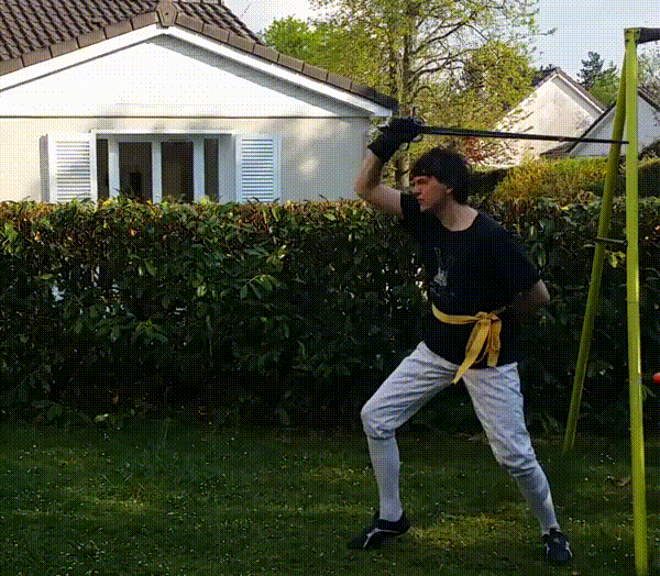
I am of course not going to claim this was a perfect ideal cut. In the sequence it is likely more of a provocation than an actual wounding attack, and after running the analysis, there are a number of things I would like to adjust in my form. However, it was at a correct angle, with good edge alignment, and enough speed that I do not doubt it would have cut into a target. I would not claim it is any sort of canonical cut, but it will serve well enough to illustrate the kind of analysis that can be done.
Although the sword position was clear on every frame, the camera I used has a perceptible rolling shutter effect, which curves the blade during the cut:
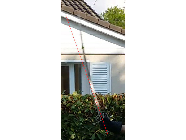
This is something that puts some uncertainty into the results, and I will try to run future experiments with a better camera that does not distort so much.
The shot was done at 30fps. This is just about enough to not miss too much of the motion, but as will be seen below the sword does cover quite a lot of distance between frames at the apex of the cut.
Time
The cut is thrown following an horizontal false edge cut, so it could be hard to pinpoint the end of one and the start of the other. I have elected to pick the instant where the sword starts to move forward as the start of the cut. From this point, the timeline is as follows:
- 0.00s The sword starts to move forward, the foot is lifted
- 0.20s Foot lands, sword almost vertical
- 0.27s Impact position (sword passing at face height), equal weight
- 0.30s Maximum extension
- 0.53s End of recovery
The difference between impact position and maximum extension is interesting to see, and indeed I did not feel the difference while throwing the cut. It is due to a combination of maybe lowering the hand too fast, or starting from too low, and the weight transfer to the front foot occurring after passing through the impact position. It is one of the things I would like to experiment further with in the future.
The time to reach the target (0.27s) is only slightly superior to the time needed to recover and stop the sword (0.23s). The whole cut takes place in about half a second.
A primer on motion
In order to productively discuss the details of the sword’s trajectory, it is necessary to lay some foundations about rigid body motion. A rigid body is an object that is assumed to be non-deformable. It is a pertinent model for the sword in this situation.
We will also assume that the sword is moving purely in the camera’s plane. The cut is very much vertical and the angle can be checked on the front view – I am confident enough that I have cut at the same vertical angle on both takes.
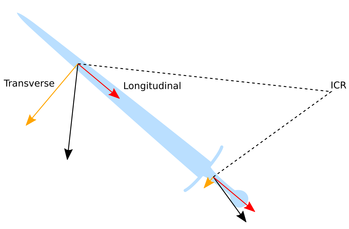
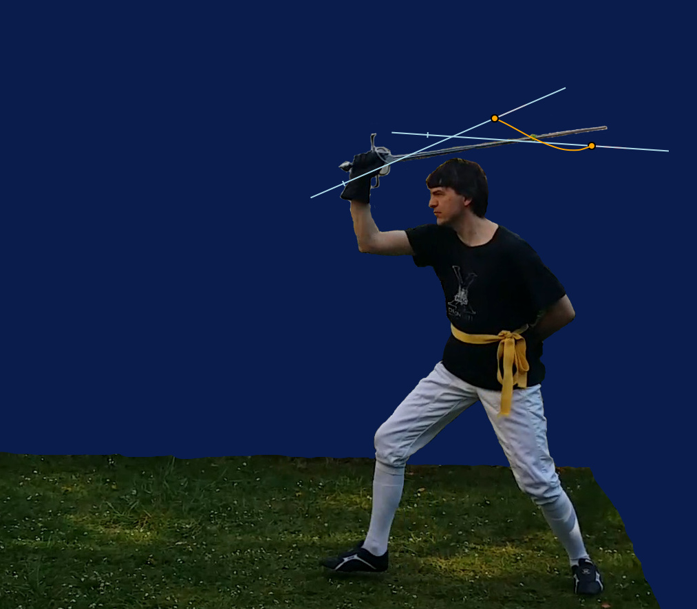
A rigid body motion lays a number of constraints which make it such that the speed of each of the points on the object are not independent. To be specific, at any instant, the motion of the sword is a rotation around a point called the Instantaneous Center of Rotation (ICR). However, this does not mean that the sword is always rotating about a fixed point. Indeed the position of the ICR continuously changes through time.
The speed of every point can be separated in two components, one longitudinal along the axis of the sword, and one transverse. Only the transverse speed contributes to impact force. The longitudinal speed can also contribute to cutting through a different mechanism: a slicing effect. The longitudinal speed is the same for all points of the axis; again this is a property of rigid body motion.
On the figure below, you can see the ICR, the speed at two points, and how the speed can be decomposed in transverse and longitudinal components in a simple vector projection.
Trajectory
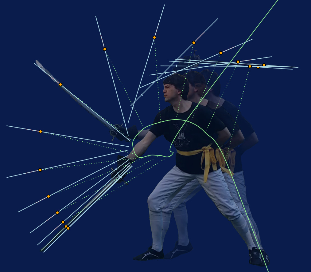
In many discussions of cutting mechanics the motion of the sword is approximated as circular, centered on a variety of body articulations. However looking at this cut, it is obvious that the sword is absolutely not moving in a circular trajectory, about any point.
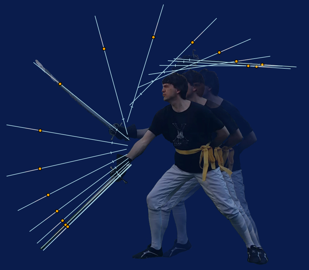
Visualising the ICR only reinforces that observation. It is very far away at the beginning and end of the cut, but comes very close to the wrist during the actual cutting portion.
This being said, there is still a circle that can be seen. If you draw the trajectory of the blade node, here is the path that you find:
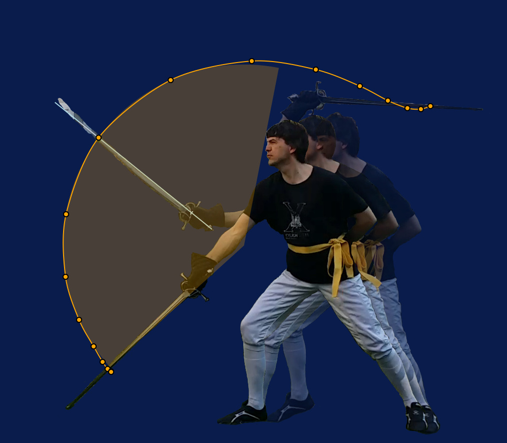
As you can see, there is a clear circular portion, highlighted by the orange transparent angle sector (this covers the interval 0.2 – 0.55s). It is notable that this circle is not centered on any particular body articulation, rather it happens due to the coordinated motion of all the joints of the body. Our brain is remarkably good at managing such complex combinations of rotations, that would be a headache to explicitly compute if we had to!
Speed
The peak transverse speed happens very near 0.27s at 13.6m/s, with a slight pulling action of something like 0.5m/s:

This level of longitudinal speed might not seem much, but it is quite significant from the point of view of slicing: drawing 5cm of blade in one tenth of a second is more or less how you slice vegetables in the kitchen. The longitudinal speed dies off and even reverses as the blade crosses the impact position, but of course the presence of a target would significantly alter the trajectory.
Energy
Kinetic energy is a useful measure of the work necessary to get an object moving, or of the work that an object can apply to a target (more on modelling impacts here). For a point mass, it is simply mass times speed squared. It is a bit more complex for a sword, which has more degrees of freedom and mass distributed along its length. It is possible to further partition it in two:
- A blade part, corresponding to the energy of the effective mass at blade node, moving at the transverse speed
- A residual part, corresponding to all the other degrees of freedom (longitudinal motion and speed of the hilt, in this case)
This is an application of the two-mass equivalent object detailed here. Of course one has to know all the mass distribution properties of the sword to compute energy.
Here is how the total kinetic energy and its components evolve through the cut:
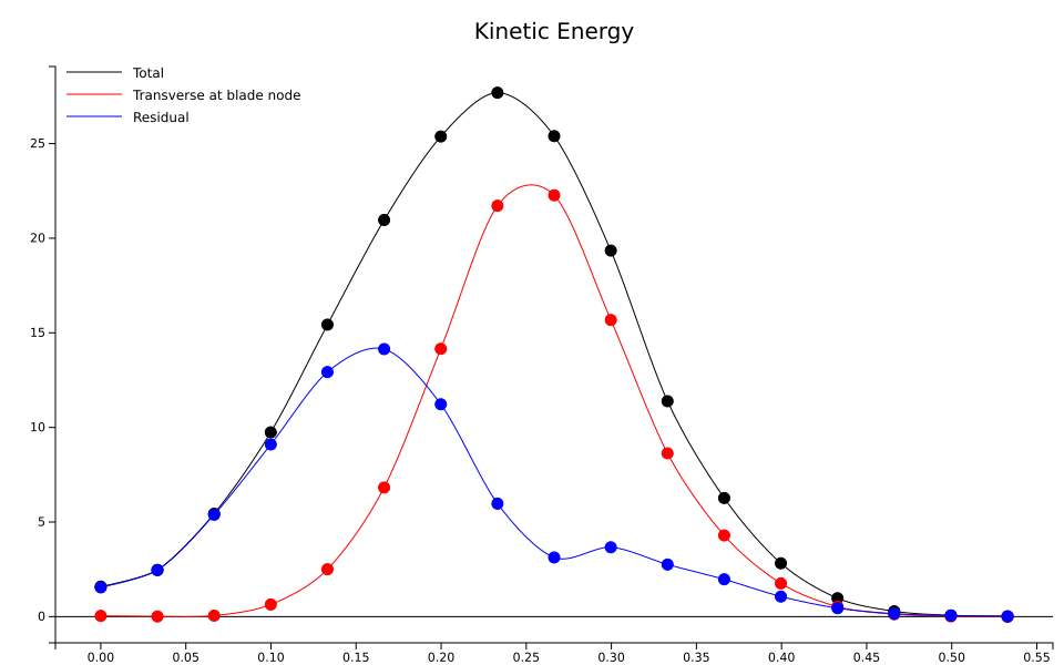
The top total kinetic energy is 28J at around 0.23s, but the top transverse energy at the blade happens a little bit later at 0.26s and is 23J. There is also a peak in residual energy at 0.15s which we will discuss in more details below.
To convert back to forces, we could consider an elastic material stopping the sword within 5cm. In this case the maximal force is twice the energy divided by the penetration depth, which gives 920N here, almost the same as the weight of a 100kg mass.
Power components
On the energy graph, we can see that not only does the kinetic energy rise and fall, but its components do not peak at the same time. It seems there is a form of transfer at play, and to investigate this we need to delve into the causes of variation of kinetic energy and its components. The variation of energy through time is properly called power. There are various forms of power at play here: external actions, and kinematic transfers between components.
The external causes are easy to list, especially in this case since there is no interaction with a target:
- User action
- Gravity
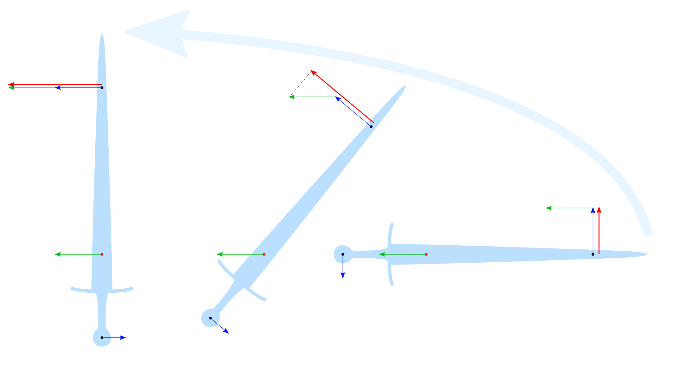
Kinematic transfers are harder to grasp. They are due to the interplay between the linear speed of the object and its rotation. If we consider a sword moving through space without any force applied to it (thrown, without gravity, basically), its motion is composed of two parts:
- the center of gravity moves along a straight line
- the sword rotates around the center of gravity
If you look at how the linear and rotational speed compose at different stages of the motion, as shown in the figure below, it is apparent that the transverse component of kinetic energy changes depending on the angle of the sword. The overall kinetic energy does not change in this case, however (no user action, no gravity). The effect is therefore that there is a transfer from residual energy to transverse and back. This transfer is entirely due to the motion of the object, hence why I chose the term kinematic power.
Powering mechanisms
There is a lot to say about these source of power and their changes through time, because it lets us peek into the power mechanisms that are used in such a cut.
Focusing first on the part that would be applied to the target, the transverse energy at the blade node, we can observe the powers from the different sources:
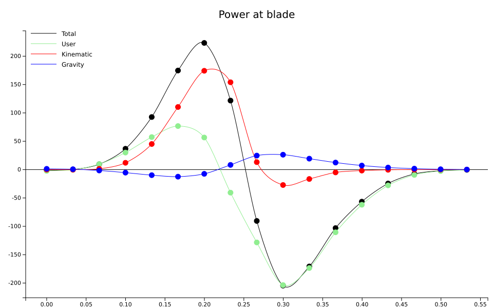
If you look at the black curve, representing the total power applied, it is fairly symmetrical, peaking at roughly 200W on either side, crossing the zero line at 0.26s, as expected given the transverse energy at blade that we have seen earlier (maximum energy means zero power, because power is the time derivative of energy). The positive peak is at 0.2s, the negative peak is at 0.3s.
User power in green has a low positive peak, of about 75W at 0.16s, and a big negative peak of -200W at 0.3s. So from the blade node’s point of view, the user is expanding most of his power controlling the blade, and only a portion of it actively speeding it up.
Kinematic power in red is even less symmetrical. It is strongly peaking during the power-up phase at 0.2s, reaching 175W, and then falls down to mostly negligible levels. This is a very important contribution to speeding up the blade.
Gravity effect is mostly negligible, never reaching further than 25W on either side. In fact, gravity power becomes positive precisely when user power becomes negative, which means that it is something that is rather actively counteracted than truly useful to the cut!
However this graph only tells part of the story. We see a lot of kinematic power, but that influx of energy came from somewhere too. Looking at the residual powers helps answering the question:
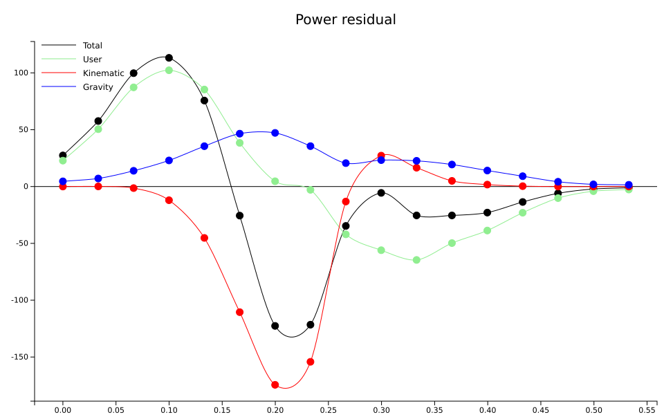
The various components are represented with the same color used in the previous graph.
The total power is not entirely symmetrical, it has a wider peak in the positive, at about 110W. The negative peak is a bit sharper.
User power is almost entirely responsible for the positive peak.
The kinematic power is the exact opposite of the previous plot: it is drawn out of residual energy and into the blade component. It is responsible for the negative peak.
Gravity power is a bit stronger here. Its peak is at around 50W. However, at the moment of that peak (around 0.17s) user power is almost zero, kinematic power is more than twice as big in the opposite direction. It does delay a little bit the peak in residual energy, but still the user is rather counteracting it. This is also true during the recovery from 0.25s onwards.
Based on these observations, we can describe the mechanics of this cut much more precisely:
0.00 – 0.15s: The user puts power in the sword, but not yet in the impacting portion of the blade, so this means mostly hilt and longitudinal motions. It is essentially a pulling phase.
0.15 – 0.25s: The residual energy transfers kinematically into the blade, with some added direct user power. This is properly the
swing
of the cut, where the sword itself is doing most of the work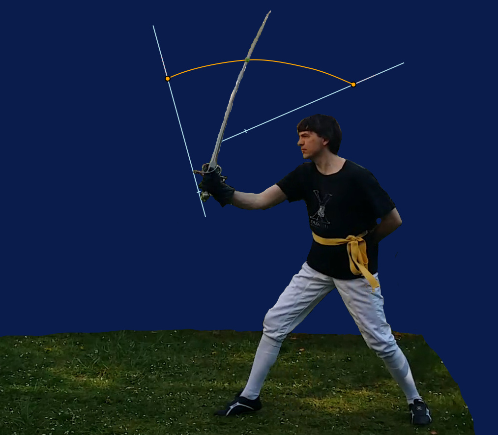
0.25 – 0.53s: A wide recovery phase, where the user absorbs power to stop the blade and the rest of the sword. Interestingly this phase starts slightly before the peak blade energy, because kinematic power transfer has to be opposed, otherwise control of the sword might be lost

The boundaries of the phases are of course a bit fuzzy. A higher framerate would be needed to draw more precise distinctions, but user power in particular is bound to change gradually anyway: our muscles do not have infinite contraction speed!
A point of note is that residual user power is mostly provided by the arm, while blade user power is much more in the wrist. It means that the weakest muscles actually have to absorb the highest peak power (-200W in the recovery phase). Inexperienced people could think mostly about pushing the sword into the cut and try to establish the structure to do so, but if structure is to be useful it will mostly be at that critical point during the recovery, and it will not be a structure to push the sword but a structure to control its speed. Speeding the sword up is not a problem; controlling it is. Arguably, my cut is a bit of a fail in that regard: I should end with the hand further back and the wrist not as extended.
A more global look at the proportions between user and gravity power confirms that gravity is not an overly important factor:

This also lets us see the magnitude of the peaks in user power: 150W given, but 250W absorbed. Gravity power never exceeds 50W.
Conclusion
The analysis gives access to many relevant quantities that can be used to provide order of magnitudes for one-handed cuts:
- Cut duration is 0.5s, half of it before impact and half after
- The speed of the cutting portion is 14m/s perpendicular to the edge, and around 0.5m/s along the edge at the time of the impact
- The energy involved in the impact is 23J, while the peak in total energy is only slightly superior at 28J
- Kinematic transfers of energy account for a significant part of the powering mechanism
- Top user power provided is 150W (75W in the impact portion), but the power absorbed during recovery peaks at 250W (200W from the impact portion). This power has to be primarily absorbed from the wrist
The more attentive readers might have noticed that I have made no mention of forces here, although the computations of powers of course assumes forces are applied which contribute to the changes in kinetic energy. I have actually attempted this but decided not to include the results because of three things:
- Force computation needs more assumptions: the points at which forces are applied
- The computation is apparently less stable than that of powers, i.e. the results are noisy
- What could be seen from the results is actually less informative than the observations on powers
I do however intend to explore this aspect further in the future.
There are lots of avenues for further research from this work:
- The use of a higher frame rate would offer more details, in particular in the fastest portions of movement
- The speed measurement could be correlated with other methods, to confirm that there is not too much bias in the estimate
- It is likely that we adapt to different lengths and mass distributions of different weapons, and it would be interesting to see exactly how. Also, how do the cut differ between one-handed and two-handed swords
- Even with the restriction to vertical cuts, there is a variety of techniques that can be used, which differ in their effects. Comparing a variety of techniques would certainly provide data that would allow a productive discussion of the trade-offs that are made
Appendices
This is the data used in this article:
- The measurements of my Danelli sidesword
- The raw data measured on the video. In this JSON file, you have an array
trackedPointswhich is a sequence of triplets(t, p, th)representing the time in seconds, position of tracked point in pixels, and current angle of the sword in radians. You also have a pair ofrefPointswhich represent the position of the extremities of the sword on a chosen frame. They are used to scale the data to correct length.
The computation of speed and powers was done using a three-point finite difference. I hope to eventually clean up the whole Javascript tool and make it available.


