Les lecteurs francophones peuvent lire cet article en français ici !
The mass distribution of swords is a well-known component of their performance and handling feel. Although sword makers have to control it through a variety of means, from a user perspective, only three parameters are needed to completely describe it: total mass, centre of gravity, and radius of gyration. They are well known of physicists. However, their values are not in direct relation with what we perceive when using a sword. Because of this, their usefulness has been questioned and their measurement in the sword community is still scarce. In this article, I will demonstrate how to build a more visual representation of the mass distribution of swords, with an application on five swords of my collection.
For the interested readers I have included more mathematical asides, which are hidden by default:
Having read my previous article here is a good way to grasp the required notions for them. I basically keep the same hypothesis, that the sword is adequately described as a one-dimensional object with a varying density along its length. Points of the sword are therefore defined by their coordinate along the longitudinal axis, and I suppose without loss of generality that the coordinate increases from pommel to tip.
The swords and their physical properties
To expose the various representations I have picked a sample of swords I have measured. These are all one-handed European swords, but each of them has a distinct character which is partly explained by mass distribution. The methods are of course generic and apply equally to two-handed swords, I have just picked a sample of swords I have at hand which presents some diversity. Here they are:
- A&A Milanese rapier
- The standard one from Arms&Armor offerings, bought in 2004.
- Darkwood rapier
- A rapier I bought in 2007, with a blunt bated rapier blade, measured here with a 3 ring swept hilt. More details about that rapier can be read here
- Albion Squire
- The standard offering from Albion Armourers Next Gen line
- AT Type XI
- An Angus Trim sword of Oakeshott’s type XI, actually the first functional steel sword I have bought, back in 2001
- Synthetic
- A one-handed nylon sword from the Knight’s Shop (similar to this one but of the first generation produced in 2010)
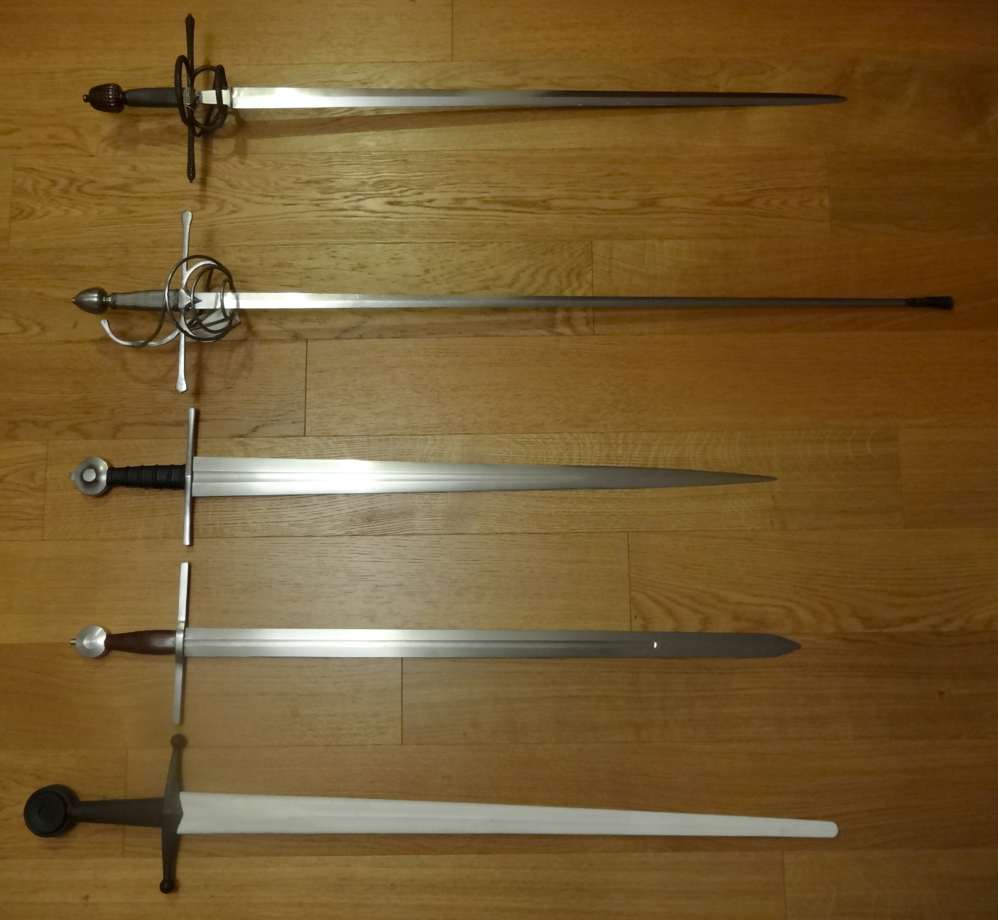
Here is a group photo of the five swords
As I’ve exposed in my earlier article, the physical properties pertinent to the physical behaviour of the sword, its reaction to forces and torques, are only three: the total mass, the location of the centre of gravity (which is the average position of mass), and the radius of gyration (which represents how far on average the mass is from the centre of gravity). Obviously, the tactical function of the sword also depends on its overall length and blade length (measured from the junction cross-handle (JCH henceforth) to the tip). These fundamental parameters are given in the table below:
| Overall length (mm) | Blade length (JCH to tip, mm) | Total mass (g) | Center of gravity (from JCH, mm) | Radius of gyration (mm) |
|
|---|---|---|---|---|---|
| A&A Milanese | 1090 | 956 | 1346 | 136 | 271 |
| Darkwood rapier | 1215 | 1072 | 1098 | 122 | 288 |
| Albion Squire | 980 | 820 | 1107 | 120 | 242 |
| AT Type XI | 980 | 845 | 1009 | 203 | 285 |
| Synthetic | 1065 | 885 | 764 | 168 | 262 |
Although all the relevant information is there, it is very hard to make intuitive sense of it. Comparing the numeric properties on their own does not give any real information on the feel that the user has. The lengths are pretty straightforward, but the mass distribution parameters are obscure. You will have to trust me on that, because this can only be demonstrated with the swords in hand. For example, although the Milanese rapier is the heaviest of the bunch, it is actually more agile than the type XI. The Squire has its centre of gravity about as close as the Darkwood rapier, but is actually more blade-heavy. The radii of gyration are difficult to interpret as well…
More than the parameters themselves, it is their interactions that define the feel of the weapons, and these interactions are not well represented on a table such as this. The problem is also multi-dimensional, and building some sort of intuitive visual representation would be helpful for the quick analysis, comparison and communication of the results. This has led me to the developments described in the next two parts.
Two-mass equivalent
Once I had learned about centres of oscillation, a very natural idea was to use them. When you have a pivot point and the associated centre of oscillation, two masses can be placed at each point, linked by a massless rod. This system of two point masses that has the same mass, centre of gravity and radius of gyration as the sword. It means that it reacts to forces in exactly the same way as the sword, it is equivalent to the sword. It goes without saying that this system is a lot easier to apprehend than the complex mass distribution of a sword and makes more intuitive sense too. This is the base of my previous article.
I have elected to put one of the point mass at the junction cross-handle as it was an easy point of reference. Then the only remaining parameters are cross mass, blade mass, and blade mass location, that I measured from JCH and called the dynamic length of the sword. Here is what happens in a table:
| Cross mass (g) | Blade mass (g) | Dynamic length (mm) |
|
|---|---|---|---|
| A&A Milanese | 1074 | 272 | 674 |
| Darkwood rapier | 931 | 167 | 801 |
| Albion Squire | 888 | 219 | 606 |
| AT Type XI | 670 | 339 | 604 |
| Synthetic | 542 | 222 | 577 |
The data, once processed in this form, also lends itself well to a graphical representation! Here is how it looks:
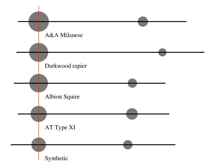
The two-mass equivalent for the five swords
The black line represents the longitudinal axis of the weapon. The red line represents the junction cross-handle, all the swords were aligned according to that point. The area of the grey circles represent the magnitude of cross mass and blade mass, and the two masses are separated exactly by the dynamic length of the weapon.
That two-mass system makes a lot of sense; you can see how the rapier has a low blade mass, how the type XI has the biggest, with the others in between. You also have an idea of the partition between hilt and blade, with the rapier being quite cross-heavy and the type XI rather blade-heavy. The dynamic length is more difficult to interpret, but basically the longer it is the less tendency the weapon has to swing in cuts. Another advantage, which I have exposed in my article, is that it can be directly measured without any need for a computation. If you start from the basic dynamic data from the last section, the computation is not really hard either; again this is described in my article.
Let us pick a weapon, with mass \(M\), radius of gyration \(k\), centre of gravity \(G\) of coordinate \(g\) on the axis of the weapon. We are looking for an equivalent object in the form one mass \((1-\beta) M\) at point \(H\) of coordinate \(h\) (here the junction cross-handle), and another \(\beta M\) at point \(P\) of coordinate \(p\) (unknown). Defining the masses like this ensures the total mass of the equivalent system is indeed \(M\). All that remains to be done is find \(\beta\) and \(p\) so that the centre of gravity and the moment of inertia around any point is conserved.
The equation giving the centre of gravity is:
\(
M (g-h) = \beta M (p-h)
\)
and for the moment of inertia, let us consider it around point \(H\), since it cancels the mass that lies at that point:
\(
M (k^2 + (h-g)^2) = \beta M (p-h)^2
\)
Replacing the first equation in the second gives:
\(
\begin{align}
k^2 + (h – g)^2 &= (g – h)(p – h)\\
\frac{k^2 }{g – h} + g – h &= p – h \\
p – g &= \frac{k^2 }{g – h}
\end{align}
\)
Which defines \(P\) as the center of oscillation associated to \(H\), and allows to find \(\beta\):
\(
\begin{align}
\beta &= \frac{g – h}{p – h} \\
&= \frac{g – h}{ \frac{k^2}{g – h} + g – h}\\
&= \frac{(g – h)^2}{k^2 + (g – h)^2}
\end{align}
\)
There are three main drawbacks to this representation as a two-mass system. First it gives the wrong impression with the two concentrated masses: we see two point masses and this makes us think that the mass is somehow concentrated at these two specific points, which is not really the case. Second, it does not take the physical extent of the weapon into account: the blade mass could very well be beyond the tip (it happens on fencing foils for example, although I have not included them in this sample). Third, and most importantly, it involves some arbitrary choice. I have picked the JCH as a pivot point here, but the model might be built from any other point and still make sense. For example here is how it looks when you take a point 10cm into the hilt as the reference:
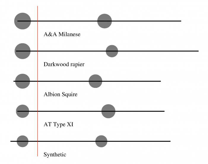
Another two mass equivalent representation for the swords, just as valid as the previous one
Which is more correct? There is nothing here allowing us to pick a choice over the other. That the representation depends so heavily on this arbitrary choice is unsatisfying. What is needed is a representation that is unique for each sword, yet generic enough to apply to many swords.
Stick and point mass
The next representation is based on a common intuitive object that has both mass and length: the stick. The uniform stick to be accurate, which has a constant thickness without any taper whatsoever. You can’t get much simpler than a stick, and it is an object that everybody is familiar with and manages to use almost instinctively from an early age. A stick is always well-balanced no matter where it is held, and is perfectly described by its length and density (how ‘stout’ the stick feels).
Swords are most definitely not sticks. However, it is possible to mathematically find how close to sticks they are by splitting their mass in two parts:
- one given to a uniform stick of the same length as the sword
- the other concentrated as a point mass located somewhere on the axis of the weapon
Using a point mass ensures we attribute the maximum amount of mass to the stick. We end up with three parameters:
- the stick density (as said earlier, how stout it is)
- the mass concentration (the ratio of the point mass over the total mass)
- the point mass location (which can be given relative to any point of reference on the sword)
You could of course pick different combinations of these parameters, but I find they relate best to my tactile feel of the swords. Here is the table as usual:
| Stick density (g/m) | Mass concentration (%) | Point mass location (mm, from JCH) |
|
|---|---|---|---|
| A&A Milanese | 422 | 66 | -7 |
| Darkwood rapier | 260 | 71 | -16 |
| Albion Squire | 435 | 62 | -11 |
| AT Type XI | 612 | 41 | -19 |
| Synthetic | 317 | 56 | 22 |
And a visual representation of the data:
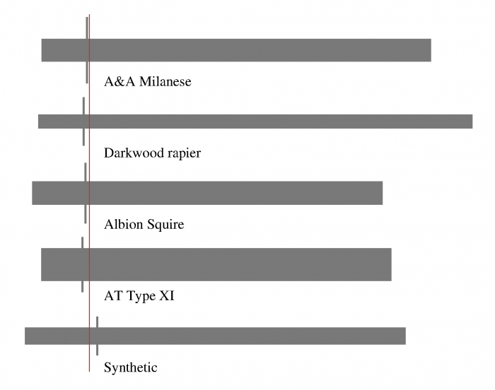
A graphical representation of the stick and point mass equivalent for the swords
Here the rectangles represent the stick mass; their thickness is proportional to the density of the stick. The vertical grey bars mark the point mass location. The ratio of the length of the grey bar and the thickness of the rectangle is the mass concentration of the weapon. Do note that this representation is entirely objective; the only thing I do is line the weapons at their cross, but the representation of mass is unique when computed in this fashion.
Brace yourself, because it is a lot harder to compute the stick & point mass equivalent than the two mass equivalent.
Let us pick a weapon, with mass \(M\), radius of gyration \(k\), centre of gravity \(G\) of coordinate \(g\) on the axis of the weapon, and butt and tip \(B\) and \(T\) of coordinates \(b\) and \(t\) respectively. We are looking for an equivalent object in the form of a stick of length \(t – b\) and mass \((1-\xi) M\), with a point mass \(\xi M\) at point \(W\) of coordinate \(w\). The mass concentration is \(\xi\), and the equation for mass is already satisfied.
Now feel free to skip to the next horizontal line if you just want the formula and are not interested in how to solve the equations…
The centre of gravity of the stick is at \(G_s\) of coordinate \(g_s = \frac{b + t}{2}\), and its radius of gyration is \(k_s = \sqrt{\frac{(t – b)^2}{12}}\) (this is a well known result that the reader will be able to easily derive from definition of the moment of inertia).
The equation for the centre of gravity is:
\(
M g = (1 -\xi) M g_s + \xi M w
\)
And we also want to have the same moment of inertia around any point \(P\) (\(p\)):
\(
M ((p-g)^2 + k^2) = (1 -\xi) M ((p – g_s)^2 + k_s^2) + \xi M (w-p)^2
\)
(this is an application of the parallel axis theorem)
Simplifying by \(M\) and reworking the first equation gives:
\(
g – g_s = \xi (w – g_s)
\)
The second one is a bit more difficult, yet it’s the one we will start solving. Let us pose \(J(p) = (p-g)^2 + k^2\) and \(J_s(p) = (p – g_s)^2 + k_s^2\). After simplifying by \(M\), the equation becomes:
\(
J(p) – J_s(p) = \xi ((w-p)^2 – J_s(p))
\)
And this is true for any \(p\). We will pick a specific value that simplifies the equation, \(p_0\) such that:
\(
J(p_0) = J_s(p_0) = J_0
\)
which implies:
\(
\begin{align}
(p_0-g)^2 + k^2 &= (p_0 – g_s)^2 + k_s^2 \\
p_0^2 – 2 p_0 g + g^2 + k^2 &= p_0^2 – 2 p_0 g_s + g_s^2 + k_s^2 \\
k^2 – k_s^2 + g^2 – g_s^2 &= 2 p_0 (g – g_s) \\
p_0 &= \frac{k^2 – k_s^2 + g^2 – g_s^2}{2 (g – g_s)} \\
\end{align}
\)
and
\(
\begin{align}
J_0 &= (p_0-g_s)^2 + k_s^2 \\
&= \left(\frac{k^2 – k_s^2 + g^2 – g_s^2 }{2 (g – g_s)} – \frac{2 g_s (g – g_s)}{2 (g-g_s)}\right)^2 + k_s^2 \\
&= \left(\frac{k^2 – k_s^2 + g^2 – g_s^2 – 2 g g_s + 2 g_s^2}{2 (g-g_s)}\right)^2 + k_s^2\\
J_0 &= \left(\frac{k^2 – k_s^2 + (g – g_s)^2}{2 (g-g_s)}\right)^2 + k_s^2\\
\end{align}
\)
Getting back to the equation of the moment of inertia, it has become:
\(
(w-p_0)^2 = J_0
\)
At this stage we have two solutions for \(w\):
\( w = p_0 \pm \sqrt{J_0} \)
But only one of these will give a positive \(\xi\) (which is what we want, in the end, to avoid negative masses that do not make much sense). The first equation gives:
\(\displaystyle
\xi = \frac{g – g_s}{w – g_s}
\)
In order to simplify a bit further let us define
\(\displaystyle
C = p_0 – g_s = \frac{k^2 – k_s^2 + (g – g_s)^2}{2 (g-g_s)}
\)
Then:
\( J_0 = C^2 + k_s^2 \)
\( w = g_s + C \pm \sqrt{C^2 + k_s^2} \)
\(\displaystyle
\xi = \frac{g – g_s}{C \pm \sqrt{C^2 + k_s^2}}
\)
For swords, you generally have \(g < g_s\), then you need to pick a minus as the chosen sign in the equations, because \(C – \sqrt{C^2 + k_s^2} < 0\).
To sum things up, here is what you need to compute the stick and mass equivalent for a sword:
\(
\displaystyle
\begin{align}
g_s &= \frac{b + t}{2} \\
k_s^2 &= \frac{(t – b)^2}{12} \\
C &= \frac{k^2 – k_s^2 + (g – g_s)^2}{2 (g-g_s)} \\
w &= g_s + C – \sqrt{C^2 + k_s^2} \\
\xi &= \frac{g – g_s}{C – \sqrt{C^2 + k_s^2}}
\end{align}
\)
Now the rapier looks exactly as it feels: a long and slender stick with a mass very concentrated at the hilt. The type XI is almost the exact opposite: a big stout stick with less mass in the hilt. The Milanese rapier and the Squire have very close stick densities, and indeed feel quite close as far as their stoutness is concerned. The synthetic simulator is not as heavy in the stick as them, and has less concentration of mass, which is why it handles differently.
The location of the point mass is especially interesting to consider. Note how close it is to the JCH on all five swords. This is quite remarkable, as the makers of these swords did not use this mass representation and therefore ended up balancing them like this only because it feels right, or is historically correct. I have computed this for a lot of swords measured by myself and others, and that observation remains true: swords are balanced like sticks with a big point mass near the cross. Of course the exact location of the point mass varies, and I’ll try to develop the functional implications of this aspect in future articles. One thing I can say is that weapons that have their point mass into the blade tend to swing very quickly and be difficult to control, while weapons that have their point mass into the hilt swing more reluctantly but are quite easy to control. A point mass well into the hilt or into the blade seems to result in an uncomfortable sword for opposite reasons. As an aside, this encourages the use of the two-mass equivalent with a mass at JCH, as it seems to be a peculiar location for the mass distribution too.
Basically the stick part is what causes resistance to motion in rotation, but also what hits the target when you strike at the weak. The concentrated mass at the hilt adds impacts to launched thrusts, and also gives stability to the parries made with the strong. Most people have the erroneous belief that mass is concentrated at the pommel, because it is an obvious big mass. This analysis shows that it is not so, the combination of the tapers of the blade and of the pommel end up concentrating mass at the cross. It shows the work of the sword makers, who have to work on the blade and pommel to achieve the correct mass distribution.
That is without a doubt the most useful representation I have come up with so far. The computational cost is more than made up by the insight gained from the result. It is a great way to communicate the balance of the sword in an intuitive, visual and concise way. The only hurdles to its use are the measurements and the computation, and I intend to contribute to the solution of these problems soon!


Back when I was first trying to convey the issue of mass distribution (long before I did any work on the center of percussion), I got some 48-inch wooden dowels (1-inch diameter) and a bunch of really big washers, which I’d duct tape to the dowel, distributed as your two point masses. I took these to a couple of conferences and said, “Fellas, these three dowels have exactly the same weight and balance point. Feel the difference.” One felt like a foil with a really heavy guard on it and was quick as lightning, one was pretty normal, and the other felt like a dumbbell and could barely be maneuvered at all.
I highly recommend making some of these as a quick and dirt-cheap way you can let people feel what you’re trying to convey, because I found that I could try to explain it till I was blue in the face and get blank stares, but the moment anyone handled the dowels, a light turned on and they understood. The basic “feel” of a sword wasn’t an intangible property reflecting the skill of the smith, or the steel, or the price, or the authenticity, because none of those exist in equally weighted, equally balanced wooden dowels with steel washers duct taped on.
I also took an angle-grinder to the weak of a horrible Indian reproduction Schiavona that handled like a meat cleaver and turned it into a very agile weapon that was snapped up the first time I showed it. I explained that I simply removed the steel that shouldn’t have been there.
This is actually a project of mine as well, but I’m procrastinating on it. I’m not much of a manual worker, see 🙂 Also, I figured I’d be better off understanding what range of parameters real swords have, so that I can build objects that are subtly distinct yet plausible as weapons.
In this regard, the study of originals is irreplaceable, as it’s the only way for us to pinpoint what the important properties (or combination thereof) truly are.